- Electrosport Speedsensor S4
- Electrosport Wiring Kit
- Crimper Pliar for connector terminals Molex type. (optional)
- QUICK WIRING CONNECTOR 9 WIRE 20 amp (optional)
- QUICK CONNECT 6 WIRE 20 amp(optional)
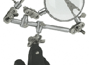
- Helping Hands (Harbor Freight Tools)
Wiring to the Stock Harness
First and foremost before starting the assembly of the wiring harness I recommend that you spend a little time familiarizing yourself with the provided wiring diagram for your make and model and the diagram included with the gauges as this write up will be biased to the stock 88 FZR1000 and the Acewell 3700 series gauge panel.

The layouts below are taken from the included Acewell wires into the female connectors. (You will not use the male connectors)Simply attach the female crimp to the wire color and plug it in.
| Nine Pin Connector Layout | ||
| [Top Notch] | ||
| Blank | Brown : → indicator (+) | Blank |
| Blank | Green : High Beam (+) | Green : Neutral Indicator (-) |
| Yellow : Oil (-) | Brown : ← indicator (+) | Black : GND |
| Six Pin Connector Layout | ||
| [Top Notch ] | ||
| Blank | Blank | Blank |
| Red(2X) : A&B PowerLeads | Black(2x) : A&B GND | Yellow : Tachometer |
:!:For the tachometer to read correctly you must change the engine cycles from 1.0 to 0.5 from the settings menu (88 FZR1000)
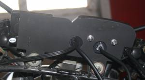
The Tachometer wire that Acewell/Electrosport supplies with the kit is extremely long for those that wish to coil it around an ignition coil. Since I intended to tap the wire into the stock harness I snipped the excess, and using a male female spade connector; I used the excess wire to run the Brown Clock Power Wire through the frame to the positive terminal on the battery (1/4 inch 22 gauge spade at the terminal). In the picture above you will see the brown wire joined to a yellow wire by way of a red spade connection.
The Speedometer Sensor is fairly simple to connect as it completely replaces the old speedometer and interfaces directly into the Acewell/Electrosport harness.
The Water Temperature sensor is a stand-alone unit that also interfaces directly into the Acewell/Electrosport unit. After discussing the stock configuration the Acewell/Electrosport Technician advised against splicing into the stock sensor and schematic. 

-ShogunTX (Inspiration by MsHap visit her site Jello's Homepage)
FZROnline.com is not affilated with Yamaha in any way. The content on this website has not been endorsed by Yamaha, nor has been verified for correctness by FZROnline.com (USE AT YOUR OWN RISK!). The Yamaha name and logos are registered trademarks of Yamaha and Yamaha North America, Inc.


