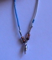
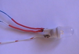
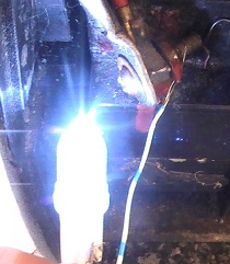
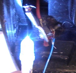
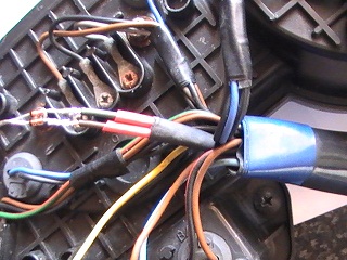
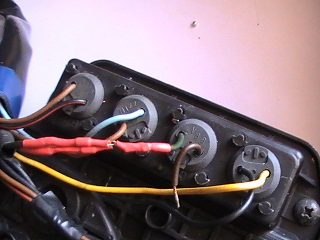
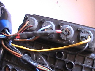
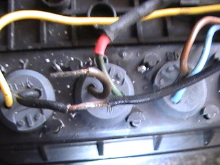
First i'll deal with the blinker/turn warning lamp, this changes polarity, power comes from the blinker's that are on, it earth's/grounds via the blinkers that are off, i.e the bulbs 2 wires are connected to right blinker & left blinker positive feeds, so we need diodes fitted. Otherwise the blinkers would act as Hazard Warning Lights.
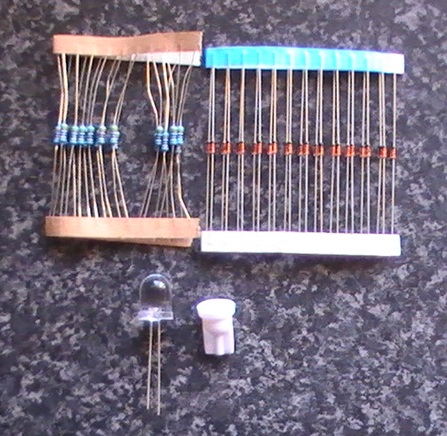
The components
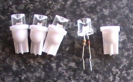
Left 1 x 430 ohm resistor, Right 2 x 1N914 100v 75mA Signal Diode, Bottom Left 1 X 10mm white led, Bottom right 1 x 10mm capless led holder
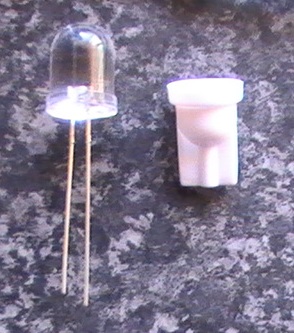
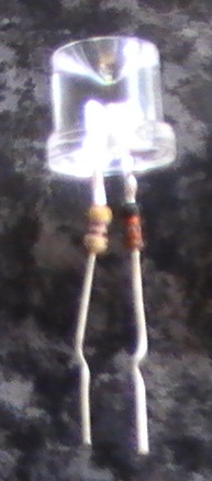
Note the long leg on the led, that's the positive (anode)
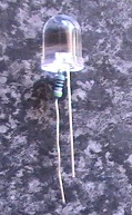
The resistor soldered to the anode, note how closely fitted to the led, not much room in the capless holders.
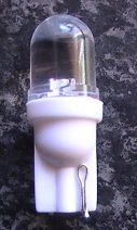
Fitted inside the holder, i've doubled the resistor leg, to identify the positive (anode) which will connect to the diodes.
The diodes soldered to some makeshift wires, imagine they are the blinker wires from the harness/loom side (light/Green dark/Green some US models, dark/Green dark/Brown other models)
Will need to cut the wires on the rubber push in blinker warning lamp holder (light/Green dark/Green some US models, dark/Green dark/Brown other models) diodes will solder to the 2 blinker wires harness/loom side, difficult to see here but there's a thick black band at one end of the diodes, bottom end in photo (your diodes could differ, so check with a ohm meter, or multi meter in the diode position) they should face the wires on the rubber holder and be soldered to either wire, make sure the positive (anode) goes in that side of the holder. The remaining warning lamp wire, will need connecting to a suitable ground. (will add photo's when i get round to doing the mod) was difficult to explain without, does it make sense?
All wired up. I've used White/Orange for ground, Blue/White to 1 diode, White/Blue to the other. Simply cause it was lying around :)
White/Blue connected to battery positive, led illuminated
Blue/White connected to battery positive, led illuminated
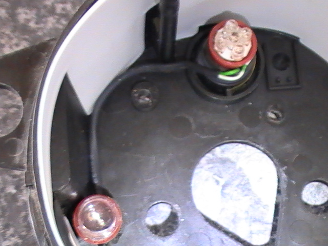
After pi**ing around putting the led together, i remembered i had 4 pre-made ones :duh: got them off eBay for around £2, was going to use them for my dash lights, but opted for Red led's (bikes Red)
pulled 1 open to identify the anode, the resistor (left leg) is the anode, diode (right leg) is the cathode, diodes there to protect against reverse polarity (led could blow)
So all you need is 4 leds around £2 $3, may as well change the oil, high beam, and neutral warning light's, 2 diodes a pack of 25 is around £0.75 $1, some heat shrink, or electrical tape,
Those led's come in all colour's and are a direct replacement for your dash (speedo, tach, and temp) gota make sure anode (positive) connects to the positive wire (think it was Blue) mine where 3 x 10mm leds 1 x 5mm led, if the dash is dim, you need to open the dash, there's covers over the stock bulbs that need removing, i fitted an extra 10mm led under the 30 MPH position, fixed it with double sided foam tape to the speedo body (mine was dim in the low MPH area).
LED's don't get hot use less power, have a long life span, and do not have filaments which when hot can burn out and suffer from vibration stress. coloured ones look pretty in the dash :) But stick to white for the warning lamps.
Does that all make sense? :)
Ok i done the mod Yesterday
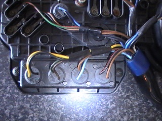
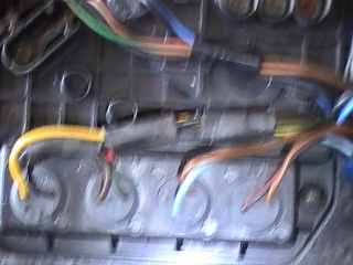
The rear of the warning lamps, the lamps left to right
High-beam, Yellow Positive, Black Negative
Turn/Blinker, dark/Green Positive, dark/Brown Positive (light/Green some US models)
Neutral Brown Positive, light/Blue Negative
Oil, Brown Positive, Black/Red Negative
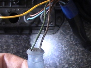
Remove the tape from the wires
We need to cut these wires
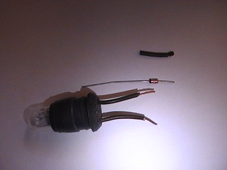
The holder cut off, i left around 1 inch of wire on the holder, the small piece of wire top right i cut that amount from both wires loom/harness side, so the wires tuck back in tidily don't want them to long
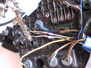
Solder the diodes to the blinker wires, make sure the diodes are the correct way round, otherwise the 12v current wont flow (diodes allow the flow of current in 1 direction only)
Now for the heat shrink, make sure it's far enough away from the soldering area or it will shrink as you solder, and long enough to fully insulate the diode legs loom/harness side
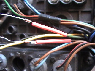
Add another length of wider heat shrink (Black in photo) over both diodes
The diodes soldered and heat shrinked to the lamp holder, i chose the dark/Green wire but its unimportant
The wider heat shrink in place, a nice weather proof seal
Now we need a ground/earth, the high beam is sat next door we know Yellow is Positive, so the Black is an ideal ground/earth to splice into, i bared the insulation back with a utility knife, then soldered the 2 wires, and insulated with self-amalgamating tape again a nice weather proof seal
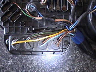
Taped up and finished (sorry for the blurry photo), just need to fit the other 3 led's make sure the anode (Positive) goes to the corresponding lamp positive
High-beam, Yellow Positive, Black Negative
Neutral, Brown Positive, light/Blue Negative
Oil, Brown Positive, Black/Red Negative
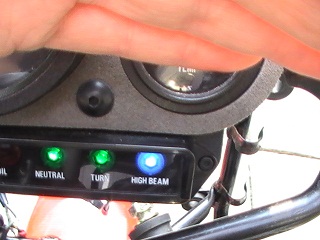
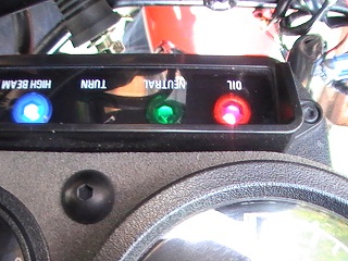
The led's working
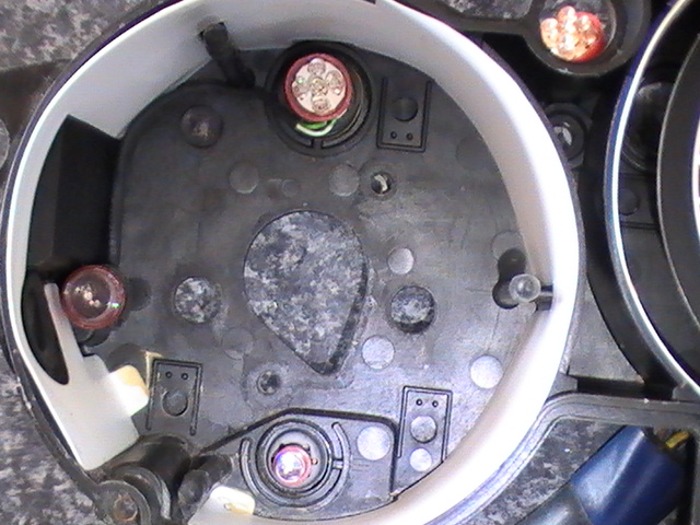
Inside the speedo lamp covers removed, you may need to do this depending on how bright your led's are (i had to) 10mm led top, 5 mm led bottom, the extra 10m led i added side
Close up of the extra led, i soldered it to the top led legs, fixed it to the speedo body with double sided foam sticky tape
Mawler (English Chapter of FZROnline.com)

