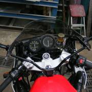
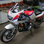
FZR600 forks fitted with PD Valves / Cartridge Emulators
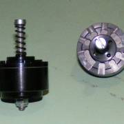
This is what I intend to install. They are PD Valves (Cartridge Emulators in American speak) from YSS suspension.
I bought mine from Greg Fairthorne of ASR suspension in Victoria Australia +61 3 5981 0165 simply because the American dealers were hassling me over shipping/credit card and any other rubbish they could think of NOT to sell to a UK buyer.
Greg on the other hand took my credit card details & put the goodies in the post and 7 days later, they were gracing my desk for the above photo. In Oz speak “good on yer mate”
To go with my new valves I decided to buy new springs. I had a funny suspicion that the springs on the bike were the original from the YAMAHA factory!
With all the hassle of dealing in America I found a spring maker about 20 minutes from home, Craftsman Springs +44 (0)1895 811 797 talked to Russell who gave me an excellent price for the pair at 40 quid collected.
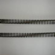
The ones in the picture are a linear 0.80Kg/mm, which is what was recommended to me for my weight & riding style. Russell will happily make what ever you spec
You will need the spring rate in Kg/mm, spring length in mm, outer diameter in mm, and the spring travel required in mm. Other things to buy is a liter of your favorite fork oil in whatever weight has been recommended (15 in my case), new oil seals & dust caps.


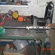
The above photo's show the fork tool I made for removing the damper rod Allen bolt in the base of the shock. It is a piece of 1/2 inch sq. steel bar 30inches long with a nut that is 24mm across the flats welded to the end. The first photo shows how I use it in a vice (which is why I use square bar) so that the fork leg can be slid over the tool with one hand and locked in place , whilst the other hand uses the Allen key to undo the bolt as shown in the photo below.
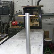
The above photo's show the seal tool I made for replacing the fork seals squarely in one smooth move.
It is a piece of steel pipe 19.5“ long & a 40mm bore. The business end MUST be burr free.
Place the seal on the inner tube with the inner tube fully compressed in to the outer fork tube. Slide the tool over the inner tube and allow the weight of the tool to push the seal in place.
Well that is enough about the prep & tooling required
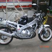
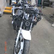
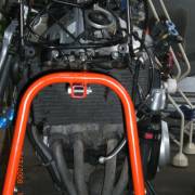
As most of you are aware the FZR is a pigs ear of a bike to work on! It has NO center stand & no Lift bobbins on the swing arm ! To work on my bike I removed ALL the fairings,
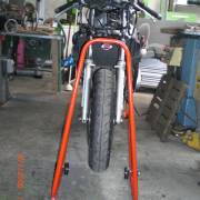
I then used a spigot type front race paddock stand
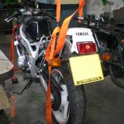
and then used a ratchet tie down strap over a roof purlin ( an alloy ladder in this case). Attaching the two hook ends to the passenger hand hold bolted to the rear sub frame & richeting the whole bike up so the back wheel was level off the ground to the front wheel.
well with the front off the ground the brake calipers were removed from the fork lowers. With them out of the way the Front axle can be unscrewed. the bolt head is 17mm a/f and has a 30mm diam ” washer “ built onto the nut to spread the load. The shaft is 15mm in diameter and the plain area is 210mm long with a 14Mm thread 26mm long at the other end.I note this here as these will be the basic notes for a FAT axle modification investigation.
The next action is to remove the drop bars (handlebars) being careful not to lose the roll pins that position the bars in the right place
With the bars off the removal of each fork tube can be done. At this point if you do not have the tools I made available you may want to slacken the allen bolts that hold the damper rod in place (if you are lucky ). You may also want to loosen the fork cap bolts whilst the top clamp is tight and acting as a vice, if that fails loosen the top clamp ONLY and try again By slackening the triple tree clinch bolts the fork will drop suddenly so a} hold them and b} mind your toes LoL.
OK, with the forks out, hold one vertically and carefully remove the cap bolt REMEMBER this is under serious pressure from the spring !! Once the cap is off remove the spring,place it on several sheets of newspaper since it holds lots of old oil and crud. Drain the oil from the shock body by inverting over an old pan.
Now the bulk of oil is out you can undo the oil drain bolt on the side and pump out any residue of oil, replace the screw loosely and pour white spirit into the shock only 2-3 oz is required, pump the shock and remove the drain bolt once again & pump out the mixture.
With the bulk of oil & muck removed you can think about removing the damper rod with the tool I showed you. Once the rod is undone the inner tube is almost ready to be removed from the outer.
Remove the dust cap if you have followed the seal replacement how-to on the FZR Online community and purchased new dust caps and seals.Then care is not a requirement of removal EXCEPT to NOT scratch the inner tube.
With the dust caps out of the way you can now CAREFULLY remove the lock wire spring thingy that stops the oil seals moving.
You can now use the inner tube as a slide hammer to remove the seals care should be taken at this point to NOT drop the innards all over the floor.
Things to collect for re-use the damper rods and the nylon oil stop bushing and the rebound spring and the allen bolt (if you had not previously removed & stored on one side)
All parts should be carefully washed in White spirit & blow dried with an air line OR the Girl Friends Hair drier on COOL / COLD Setting
Right so with all the bits clean and ready for use we need to start Parts Tuning & Assembly Process.
The first thing that needs setting is the spring pre-load on the PD valves themselves. The advice given by Greg at ASR suspension was not to rely on factory preset values but start from scratch & do the set up yourself.
Back the screw out until it is leaving the spring free to move up and down the screw length freely. Now SLOWLY turn the screw in till it just touches the spring BUT without putting pressure on it (NB . this is tricky but well worth the effort of doing correctly)One thing I do wish the factory had used was a posi-drive / Phillips head or allen socket headed screw.Next time I just may measure the thread and replace it as it looks to be 3 or 4mm
Once you have found this magic spot add 3 full turns to the screw (for me at least)the factory base line is 2 and Max of 7. Having done this on both PD Valves set them aside to use.
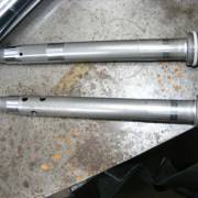
The stock damper rods are not “jetted” for the PD valves.
The top one shows the stock hole (one of a pair at the same height)at the left hand (bottom in use) end
The bottom Damper Rod has been modified according to spec. The bottom pair of holes are bored out from 3.4mm to 6mm. the next pair of holes is offset by 90 Degrees and 10mm (centre to centre) again 6mm in diameter above the original set the 3rd pair are again offset by 90 degrees (ie back in line with the originals )and 10mm above the second set or 20mm above the originals (center to centre)) 6mm in diameter
It is EXTREMELY important to remove all machining chips from the damper rod bores and deburr the inside and outside of each hole.


with the damper rods clean & modded we can place the short rebound spring back on & place them inside the inner tube and put the plastic oil stop gizmo on the end of the damper rod when it sticks out the lower end of the inner tube. Carefully place the fork outer over this inner & damper assembly, I found this very easy to do using the fork tool as it stops the damper rod moving around and losing the oil stop plug in the process. Now be sure the copper washer is in the fork bottom lock bolt hole and carefully screw the allen bolt in. Torque it up one time, also tighten down the oil drain plug.
Now comes the tricky bit which is to put the inner tube down as far as it goes and set the oil height. Now i normally pour until I can see oil at about 1.5” below the top of the inner tube and use a vet's syringe with a piece of clear hose instead of a needle (mate's use a turkey baster (thanksgiving turkeys get a new baster I hope)) the length of the hose is cut to the required air gap {in this case 120mm} Push the plunger right down and insert into the oil and draw up the oil until you see continuous bubbles:-}
With the oil level set, drop in the PD valves with the screw heads upwards. They tend to sink somewhat slowly. You then insert your new spring slowly and place the original self centering washer on top of the spring. Pull up the inner tube gently.
The next bit is a little tricky as you need to set the spring pre-load spacer length as your original spacers will be way too long with the PD Valves in place
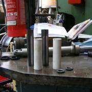
The above pic shows the old metal spacers & the new plastic ones with the OEM self centering washers
First measure the pre-load spacer you have and deduct the thickness of the PD Valve from that & cut it perfectly square, a tube cutter or Lathe is useful for this.
Next place the shortened spacer into the inner tube and mark where the inner tube top edge comes then and deduct the fork cap length of thread from that & ADD the pre load depth back on top of this line (in my case is 18mm) & cut it square again.
Put this fork back into the triple tree DO NOT Drop it or you will need to reseat the pD Valve and spring and set the air level above the oil again. Tighten the lower clamp first with the fork well above the upper triple. Place the fork cap into the inner tube (sounds easy but you are dealing with 18mm pre-load and a very fine thread which is REAL easy to cross thread)
With this latter problem I tend turn the wrong way on the cap so that it will “click” as the two screw thread ends pass each other.
I then turn the correct way and the threads immediatly line up. This is also very useful for the “self tapping ” screws used in the fairing infill so as not to strip the plastic lugs. Repeat this process with the second fork leg.
I removed the fork legs after tightening the 2nd fork cap to the right torque so that i could have free access to the old oil filter as I intended whilst the bike was in the workshop to replace the old oil & filter plus the coolant of unknown ancestry. The how-to's for these operations are at:- FZR Online community
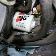
The rather nice K & N Oil filter with its handy welded top nut for installation & removal unlike the one I wrecked taking off
The odd thing I found that when I changed the coolant to use the “Engine Ice” was that when I filled it back it used onlt 2 ltrs and that was also part filling the over flow bottle. Despite tumbling the engine and letting it warm up for 15 odd minutes the level did not appear to alter anywhere but it did just clear off the C block on the guage. By now the shop workers were slightly tired of the exhaust noise LoL. so I relented and switched it all off and re-assembled the front end.
I also received (slightly later than expected due to the lazy deliver persons the new double bubble screen from my mate Alan at Alkamto on E-bay OR Alkamoto Body work supplies Dealt with him for years and a good guy to find that odd bit of body work either S/H or replica. Top Man Alan.
One of the sharp eyed workers at my mate's work shop , Tony, he of the welding skills fame, spotted that the magneto cover was not only scratched but cracked from the PO fall prior to its arrival by me.
So out came the allen keys, and off came the cover this is a bit of a hassle since the generator core windings are bolted to the cover and are under the influence of the Flywheels magnetic force.
I had to use an Impact screwdriver to remove the 3 screws holding the cables in place & some elbow grease to move the 3 allen bolts holding the coils
with the cover now free I drilled the ends of the cracks (to stop them spreading) and wire brushed the paint off.At this point I called over to Tony and reminded him that no good deed should go un-punished and could he kindly weld the crack closed inside & out.
This took quite some time as the alloy casting heated up very fast and would have proved to be troublesome except for Tony's expert workmanship. with the whole thing cooled by air it was time for my handy work again.
I ground down and filed the weld bead & I also filed some of the rougher gouges and body fillered the scrapes. I then rubbed the whole mag cover prior to filler undercoating.
That undercoat was rubbed down to a perfect finish and i then sprayed it with “Rover Gunmetal” car paint which it turned out to be a darker silver than the Yamaha version of Silver on the bike. I must admit that if I had not JUST changed the oil I would have been tempted to do the Peanut cover and the Clutch cover to match and had a rather tasty two tone silver bike. But alas I was not about to do that so I went out and bought the “Peugeot Aluminium” car paint which is as close as Dammit to the Yamaha Version
Well with the bike re-assembled I wheeled the bike outside into a hazy summer day said bye to Len {the boss}& Tony {floor chief} and rode off. Now normally I hear the front end clunking away as it makes its way over the truck size pot holes of the industrial estate but NOT this time Oh what a change.
Out on the open road she just works, and stoppies are no longer frame jarring thuds, wheelies are gentle returns to earth feather light at the dab of back brake.
;-)AHH the smile is so wide… making the helmet a hassle to remove Job done.
- Submitted by Yamaha George visit his site Saltmine.org.uk
