Hi, folks.
Ok, it's official - I'm back at it trying to re-invent the M-max box. if some kind soul could measure the resistance between the Red/bLue and Green wires at the speedo, both static and with the wheel turning as fast as you can get it going, it would be greatly appreciated.
Help wanted with 3TJ / 3EN
Moderators: Site Director, FZR Forum Moderators
Help wanted with 3TJ / 3EN
1989 3LN1 FZR250R, currently stock.
TTR Ignition Systems
TCI Repair and Ignition Transistor Upgrade
VRR Adaptor Harness
YZF600 TCI Adaptor
Running Light Fuse Carrier
TTR Ignition Systems
TCI Repair and Ignition Transistor Upgrade
VRR Adaptor Harness
YZF600 TCI Adaptor
Running Light Fuse Carrier
-
Evilchicken0
- Level 3.5

- Posts: 393
- Joined: Sat Aug 25, 2012 1:29 pm
- Location: London
Re: Help wanted with 3TJ / 3EN
Couldn't compare the 3TJ / 4DX and 2TK / 3EN so you derestrict the CDI's ?
The only need for this is for racing or for changing the speedo clock. If it's road riding then fit a KMH to MPH converter
The only need for this is for racing or for changing the speedo clock. If it's road riding then fit a KMH to MPH converter
Don't read everything you believe
FZR400RR 3TJ Bimota SB6
FZR400RR 3TJ Bimota SB6
Re: Help wanted with 3TJ / 3EN
Not everyone has access to derestricted TCIs. This should be a very simple - and inexpensive - fix.
1989 3LN1 FZR250R, currently stock.
TTR Ignition Systems
TCI Repair and Ignition Transistor Upgrade
VRR Adaptor Harness
YZF600 TCI Adaptor
Running Light Fuse Carrier
TTR Ignition Systems
TCI Repair and Ignition Transistor Upgrade
VRR Adaptor Harness
YZF600 TCI Adaptor
Running Light Fuse Carrier

Re: Help wanted with 3TJ / 3EN
I disconnected the guages from the main wire harness to take readings directly from the connector on the speedo. I took a static measurement. Then used an electric drill to spin the speedo cable to obtain a measurement at 35 KPH. Resistance between Red/Blue and Green wires was infinite in both cases. I was able to confirm continuity between the Green and Brown wires. (So I'm guessing Green is fine). I can't be sure whether the red wire has good continuity with-out removing the speedo. Maybe the circuit remains open until the restricted speed is reached which triggers a switch?
FZR400 (1WG): Purchased a perfectly good FZR400 with Yoshimura slip-on/EXUP, Yosh jet kit, Factory ignition advance, Racetech springs and emulators. It even had great bodywork. Like some diseased maniac I had to mess with everything good about that bike. Well, at least I have better brakes now.
FZR400RR (3TJ):Yeah, it's pink.
FZR400RR (3TJ):Yeah, it's pink.
Re: Help wanted with 3TJ / 3EN
That makes ... no sense.
Edit - more thoughts, sent as email to RD:
Ok, so where's the fail-safe check to prove to the TCI that the thing is attached?! Refresh my memory - do you have a 3TJ, or a 4DX? I know the 4DX TCI doesn't have the restrictor circuits; does the 3TJ and 4DX use the same speedo p/n?
The issue has to be the electronics aren't powered up - you unplugged them. Even if we check from the TCI end, you have to unplug it. There has to be a way to check the operation while all the plugs are connected ...
Ok - I know what plugs are used at the TCI end, and I'm going to be making a big connector order soon. I'll bring in the mating connectors for the plugs at the TCI, and make a little test harness.
Thanks!
1989 3LN1 FZR250R, currently stock.
TTR Ignition Systems
TCI Repair and Ignition Transistor Upgrade
VRR Adaptor Harness
YZF600 TCI Adaptor
Running Light Fuse Carrier
TTR Ignition Systems
TCI Repair and Ignition Transistor Upgrade
VRR Adaptor Harness
YZF600 TCI Adaptor
Running Light Fuse Carrier
-
willandrip

- Level 7.0

- Posts: 704
- Joined: Fri Sep 07, 2012 11:51 am
- Location: TYNE AND WEAR -UNITED KINGDOM
Re: Help wanted with 3TJ / 3EN
Don; I think your above post explains in some way as to how the readings I pm'ed you were also "off".
I just have had no time in garage to properly follow up.
Here is a pic of the back of 3EN2 speedo if it is of any use. (3MA 83570-00)
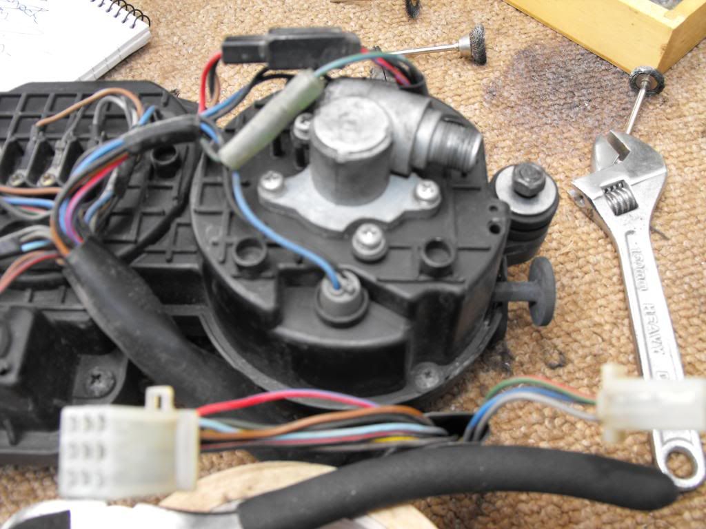
RD may have a pic of a 3TJ unit.
I just have had no time in garage to properly follow up.
Here is a pic of the back of 3EN2 speedo if it is of any use. (3MA 83570-00)
RD may have a pic of a 3TJ unit.
Sent from my keyboard using the English language not some teen text shite from a fooking phone.
Re: Help wanted with 3TJ / 3EN
I agree that my readings are inconsistent with expectations for a functional circuit. If the ECU knows whether the speedometer is connected, then it needs to receive some kind of signal. Thus, I should not be getting an infinite resistance reading on the signal wires. If the components involved are passive (i.e. some kind of resistive element), then I should be able to measure the value with-out powering on the electronics. Otherwise, I would be looking for voltage drops due to the presence of solid state devices. As long as we are dealing with passive components in the speedometer, I believe I should be able to get a measurement of it whether it''s plugged into the rest of the bike or not. If the circuit is opened by unplugging the speedo, my multimeter would close the portion of the circuit to be tested. If I take a resistance measurement with it plugged into the ECU then I will be measuring the resistance of everything in the circuit, including components in the ECU. Thus, an accurate measurement would require isolating the speedometer, no?
To clarify the test subject (my bike) is a 3TJ, however it came with a 4DX ECU. I have no idea of the history regarding the speedometer, so my next move is to remove it, and see what there is to see. Maybe the Red/blue wire is disconnected. I'm not sure which wires go where at this point, so maybe I can investigate that as well. It's all academic to me, as I'm already de-restricted by the 4DX ECU, but I'm willing to open the speedo if I need to.
What do think Don?
FZR400 (1WG): Purchased a perfectly good FZR400 with Yoshimura slip-on/EXUP, Yosh jet kit, Factory ignition advance, Racetech springs and emulators. It even had great bodywork. Like some diseased maniac I had to mess with everything good about that bike. Well, at least I have better brakes now.
FZR400RR (3TJ):Yeah, it's pink.
FZR400RR (3TJ):Yeah, it's pink.
Re: Help wanted with 3TJ / 3EN
The solid state devices may be arranged such that, in an unpowered state, the resistance is effectively that of an open circuit. The speedo needs to be connected, fed, and inspected as though connected to the TCI. The best way to do that is to connect it to the TCI. 
A little Y-harness that drops in between the TCI and the 3-way harness connector AND gives accessible measuring points for voltage, amps, and resistance through, between, and across the Red/Blue and Green wires is necessary, and will be ready in a week or 3.
A little Y-harness that drops in between the TCI and the 3-way harness connector AND gives accessible measuring points for voltage, amps, and resistance through, between, and across the Red/Blue and Green wires is necessary, and will be ready in a week or 3.
1989 3LN1 FZR250R, currently stock.
TTR Ignition Systems
TCI Repair and Ignition Transistor Upgrade
VRR Adaptor Harness
YZF600 TCI Adaptor
Running Light Fuse Carrier
TTR Ignition Systems
TCI Repair and Ignition Transistor Upgrade
VRR Adaptor Harness
YZF600 TCI Adaptor
Running Light Fuse Carrier